


This article mainly talks about the 9S12/9S08 chip and the quick wiring method.
In the daily technical support to customers, we found that it’s difficult for many CG PRO 9S12 newbies to find the wiring point and method for 9S12/ 9S08 series of instruments. It’s because some car models are not included in the CG PRO 9S12 device, the customers also cannot understand the chip pin diagram and use the multimeter. Hope this post helps you!
Part 1: 9S12/9S08 chip knowledge
Let’s go one by one!
Part 1: 9S12/9S08 chip knowledge
1.Chip model
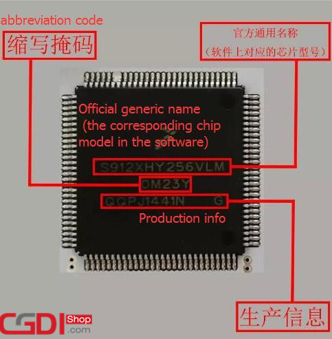
Each 9S12/9S08 chip is labeled with 3 lines of information, the first line is the official generic name (the corresponding chip model in the software), the second line is the abbreviation code, the third line is the production information.
Take 9S12XHY256 as an example below
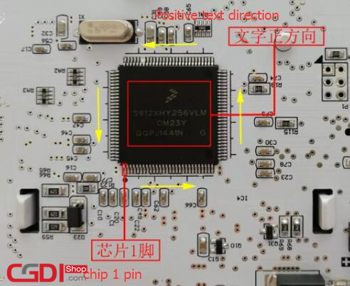
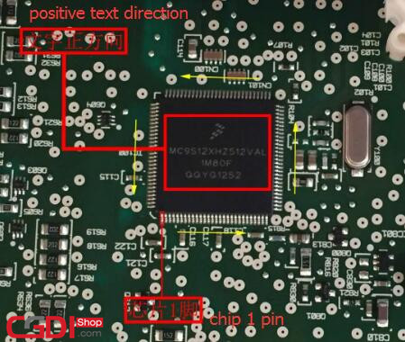
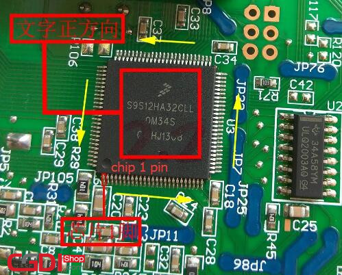
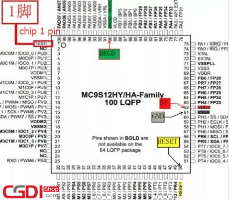
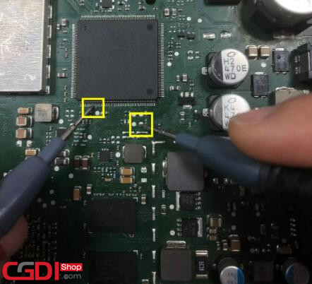
2.Chip 1 Pin
Every chip has a corresponding pin. If you find a pin correctly, you will measure out the wiring point correctly. Many customers cannot find so that failed to read data eventually, and even cause chips to burn down and cannot communicate successfully.When looking at the chip, the text above should be pointed at us directly. The chip 1 is at the bottom left corner. The following picture is the demonstration of multiple chips and the yellow arrow represents the direction of chip pin.
3.Chip Pin diagram
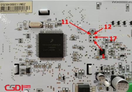
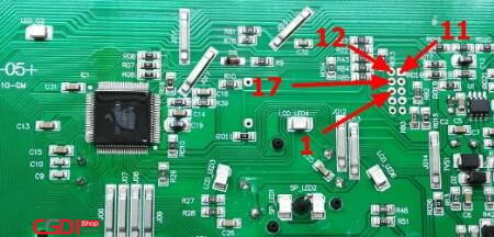
Each chip corresponds to a pin diagram which is equivalent to a human id card and contains the information of each pin, the number of pins and the meaning of pins are also specific. In the case of 9s12/9s08 series chips without encryption, if you want to read the data, you only need to weld 4 points, which are BKGD, GND, RST and 5V respectively, and the line numbers on the corresponding equipment are 11, 12, 17 and 1. (don’t be lazy to connect the wiring to the chip pin.)
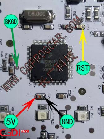
Take the 100P pin diagram of 9S12HY64 as an example
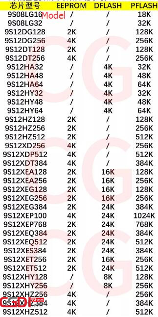
4.The size of the chip’s data area
The data area size of different chip models is different, and the value is fixed. The range area is in EEPROM or DFLASH. We have encountered many customers sending PFLASH data to the manufacturer for modification, which is wrong, so we have arranged the following table for your reference.
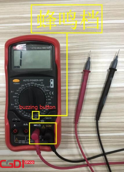
5.Measure welding point working with multimeter
Although the CG PRO 9S12 programmer has covered 80% of the models on the market, 20% of them are temporarily unsupported. Once the unsupported models are encountered, many customers will not connect the wires, and they will ask questions and make decisions after a long time. What I want to say here is that trust devices are what our manufacturers want, but don’t rely too much on them. Use them flexibly. Here we will teach you how to correctly measure solder joints and read data to repair with a multimeter.
This is buzzing button
Cross the pens together, the screen of the multimeter will display and make a sound, indicating that the gear debugging is completed
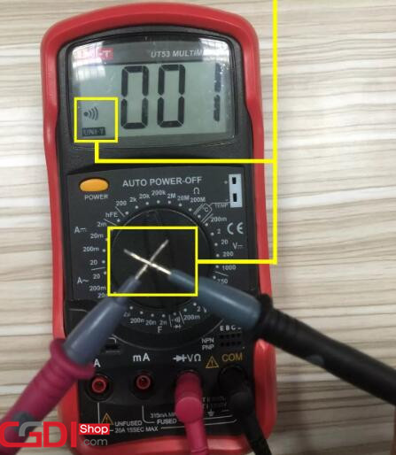
Use one pen to fix on the chip pin, and use another one to find welding spot in the module. When the multimeter sounds, it indicates the welding spot has been found, then connect.
As each meter is different, the solder joints are also different. Some of them can be seen at a glance, while some need to measure the solder joints through a multimeter. So I summarize several wiring methods for reference as below.
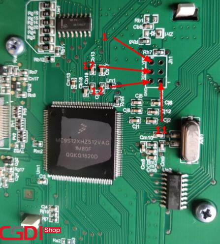
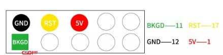
1.Standard 6-hole type
In our daily adjustment table, this kind of 6-hole welding spot meter is the most encountered and the easiest to wire. It is usually composed of 1 square hole and 5 round holes, rectangular shape. The following first figure is the general wiring, the other is the real car operation diagram.


2.Standard 10-hole type
This kind of 10-hole welding spot instrument is often encountered, consisting of a square hole and 9 circular holes, rectangular shape, connection mode and 6 holes are roughly the same, the following figure 1 is the general connection mode, figure 2 is the operation diagram of WULING HONGGUANG real car.
3.Standard 6-pillar type
This type meter is arranged by 6 identical pins and cannot see the wiring rule. It needs the help of the multimeter. Just measure out any welding spot and then polish out the other 3 welding spots according to the standard 6-hole wiring method.
Take BESTURN X80 as an example
4.Multiple row pin type
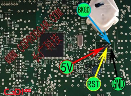
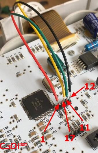
Different from the previous standard 6-pillar instrument, there is no rule for various pin pillar instruments, and the 4 welding spots must be measured.
The following picture is the actual operation diagram of CHANGAN M90.
5.Hidden solder pattern
This type of instrument is very complicated, without welding holes or pins, and it cannot be taught. It can only rely on multimeter, and the connection points need to be measured patiently.
The following figure takes Wuling Rongguang as an example.
In summary
In the chip cognition and wiring method, we need to have the following two capacities:
1.Proficiency in multimeter
2.Familiar with using soldering iron and tin
These two basic skills are not enough to master the operating principle, we need to practice more and operate more at ordinary times, otherwise we will suffer a big loss in the car repair, hope you can practice these two basic skills frequently.