


It’s difficult to identify all kinds of 8-pin chips and it needs you to contact with a variety of vehicle modules. In addition, many users often break the pins of the chip due to too much operation or too long soldering time, resulting in data loss. Today CGDISHOP.COM shares you the guide to identify and solder 8-pin chips quickly.
Part 1: 8-pin chip
1.What’s 8-pin chip?
The eight-pin chip is divided into two types: square and rectangular, and the bottom of chip can be divided into straight insert type and patch type, with four antennae on each side.
The data storage of this kind of chip is small and it is convenient to replace, but we need to deal with it patiently to test welders.
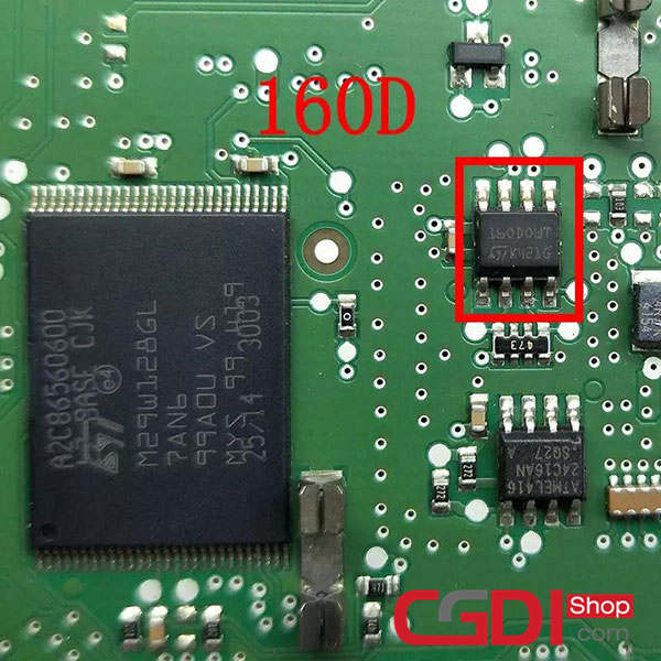
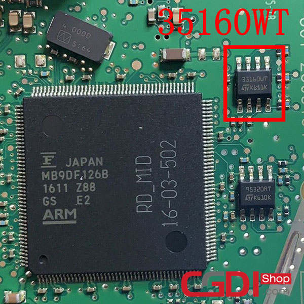
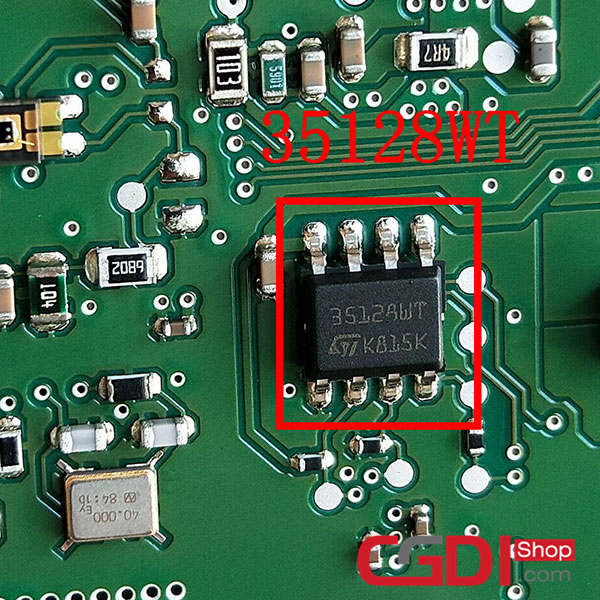
Common eight-pin chips are: 24C04, 24C08, 24C16, 24C32, 25020, 25160, 25320, 25640, 25256, 93C66, 93C76, 93C86, 93A86, 95160, 95320, 95640, 95256, 35080, 160D, 35160WT, 35128WT and so on.
2.Which module is 8-pin chip commonly used for?
In our daily work, eight-pin chips are mostly used in combination instrumentation and airbag computers, and some are used in other bodywork computers, but most of our customers are used in mileage repair and airbag repair.
3.Why are eight-pin chips so hard to tell?
This kind of situation often appears in the instrument module, usually this kind of instrument CPU and eight-pin chip coexist, or near, or on the other side, and even under the display screen, the position is not fixed, and the chip engraved mask. For newbies, only know the full name of the chip, mask for nothing, this is a test of our vision.
Part 2: 8-pin chip identification
1.Chip model determination
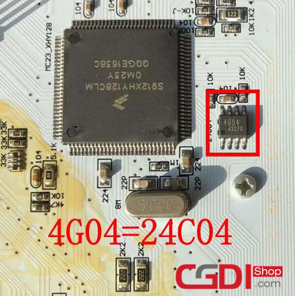
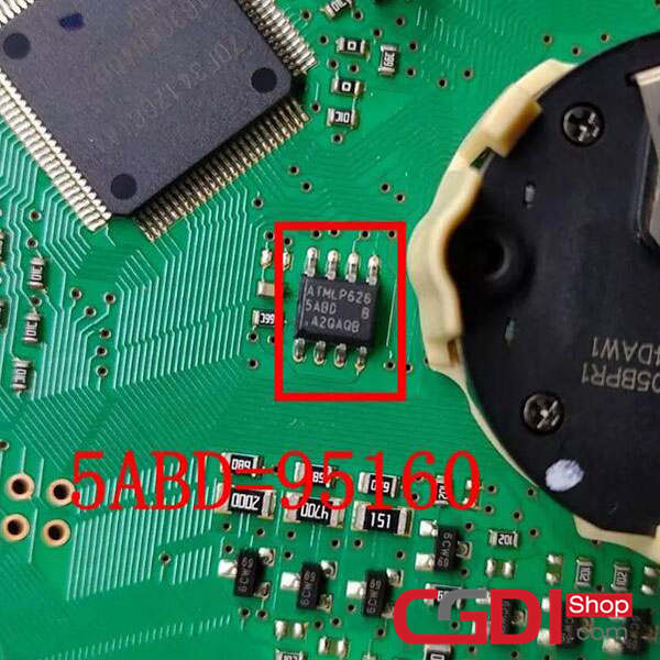
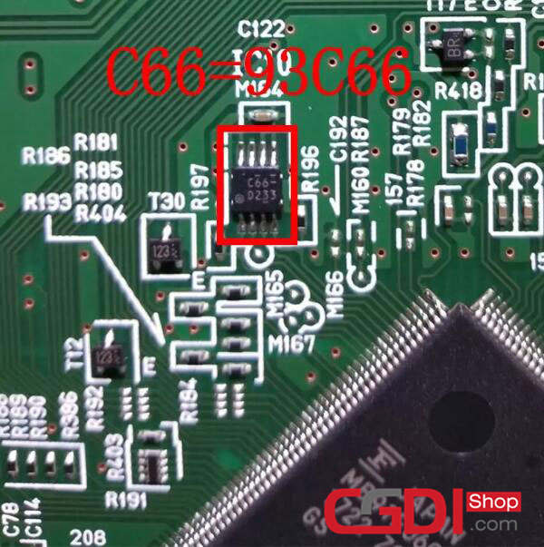
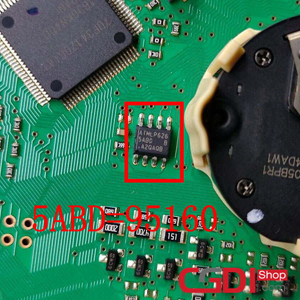
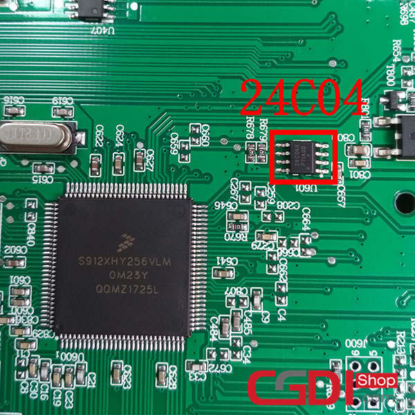
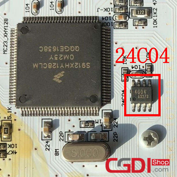
It’s difficult to recognize chip models because many of the chip engraved mask (also known as the nickname). The eight-pin chip is different from the 9S chip. It is either marked with the full name of the model or only marked with the mask, so we have to remember the corresponding mask name to be able to use it easily. There are three pictures below, the first one is 24C04, the second one is 95160, and the third one is 93C66.
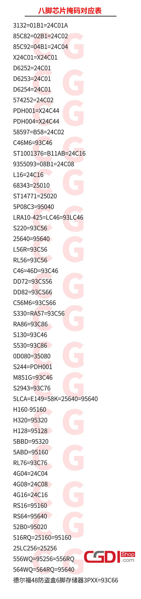
2.8-pin chip mask table
Here is a newest mask table to distinguish 8-pin chip easily.
3.1-pin chip confirmation
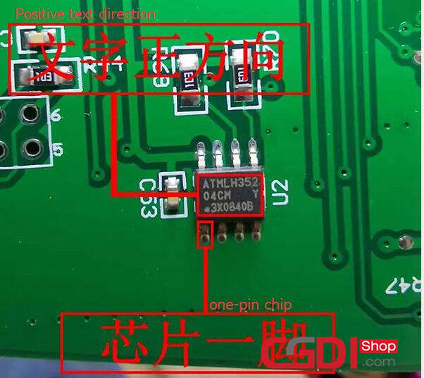
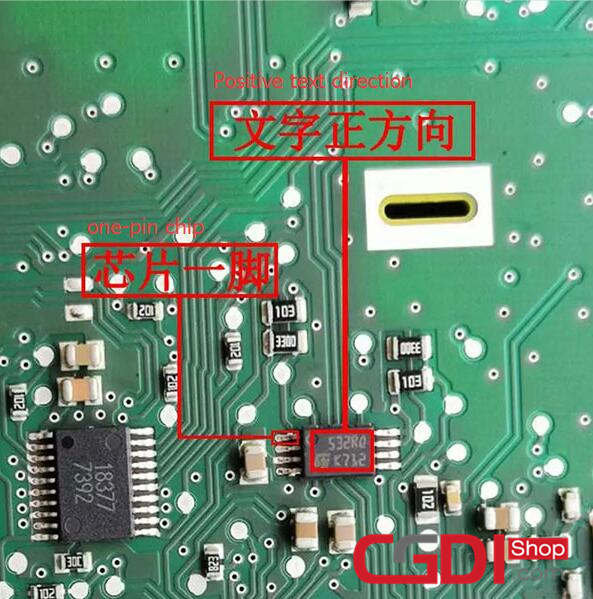
As mentioned before, the overall style of the eight-pin chip is divided into square and rectangle, and the two shapes of a foot are definitely not the same. The square chip points the text right at us, with a foot at the bottom left, and the rectangular chip faces the text directly toward us, with a foot at the top left. Using this as a standard, we can find one of all eight chips. Figure 1 below is a square eight-legged chip, and figure 2 is a rectangular eight-legged chip.
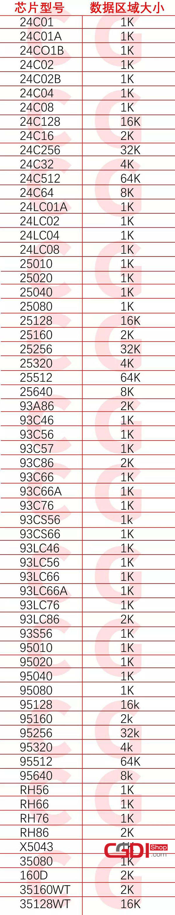
4.Size of 8-pin chip data area
8-pin chip is different from other chip types, it only has one area which can be called EEPROM, and the size of data area is also fixed. Check the form as below.
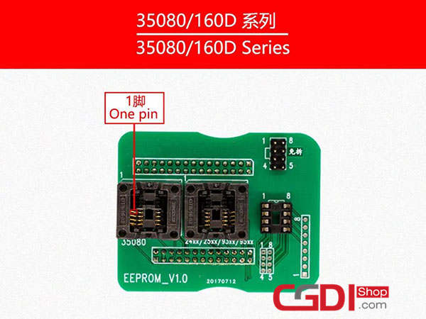
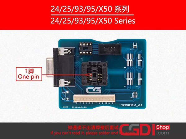
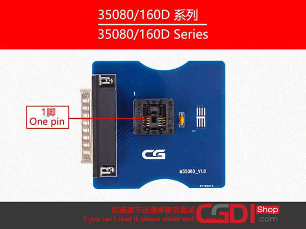
5.Adapter usage and considerations
Eight – pin chip is usually soldered off to operate, temporarily without removal. When we use an eight-pin adapter, there are two ways to read the data. The first way is to clean the chip and clip it to the adapter seat. The second way is to directly weld it to the adapter board.


6.8-pin welding direction for vehicle modules
In the process of auto repair, due to time pressure or negligence, lead to forget the welding direction of eight-pin chip on the module board, here is a shortcut to help you quickly determine the welding direction of the chip.
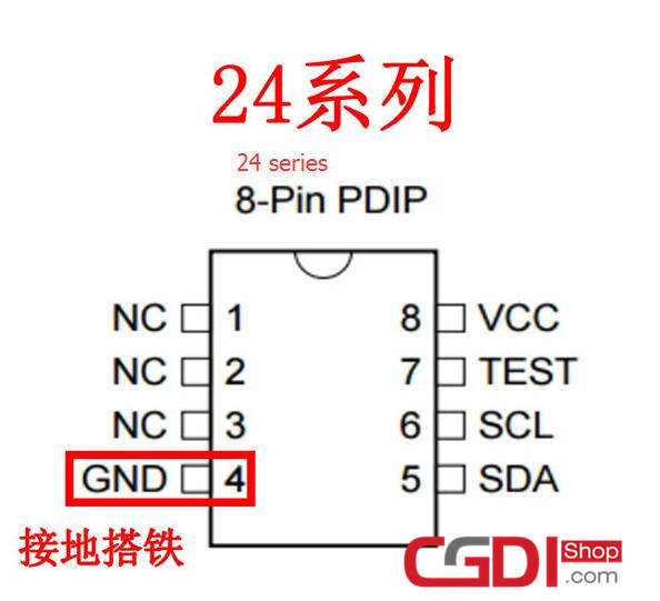
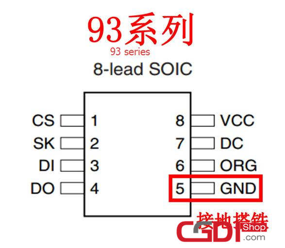
Firstly, determine the position of GND (grounding iron) of the chip welding pad on the circuit board.
Secondly, determine the position of GND (grounding iron) of the chip according to the chip pin diagram.
Finally, overlap the GND (grounding iron) of the chip to the GND (grounding iron) of the welding pad, and then align the welding.


Part3 : 8-pin chip of vehicle modules
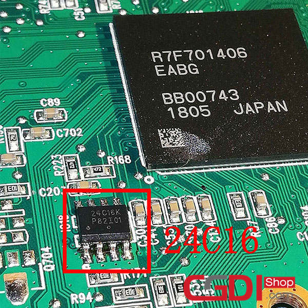
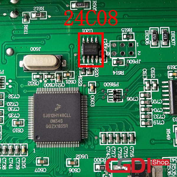
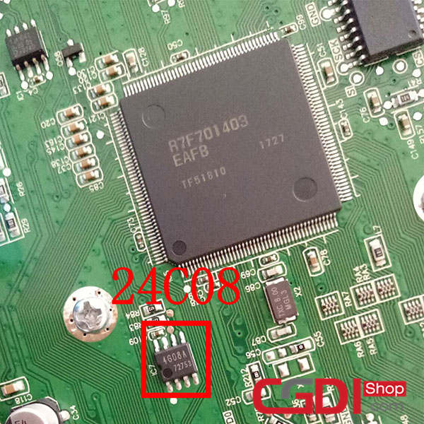
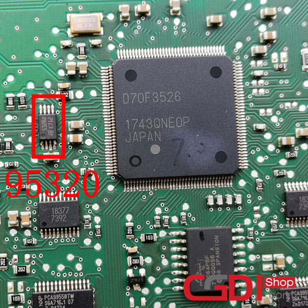
1.Hidden eight feet on the meter
In many cases, the CPU and eight-pin chip will coexist in the instrument, but the eight-pin chip will not be marked obviously, some even in the other side, and the CPU data read out is empty, such meter mileage is stored in the eight-pin chip, we need to have a very strong vision and operational proficiency. Here are some examples of instrumentation so that we can quickly find the eight-pin chip.


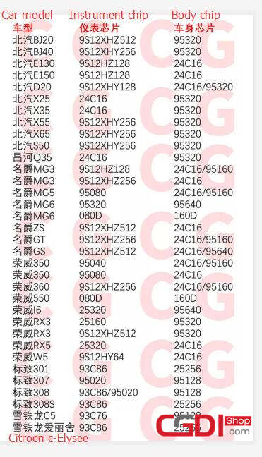
2.Instrument and body synchronization
When repairing the mileage of some vehicles, it is found that the mileage will be adjusted back after the instrument is operated. In this case, the body data needs to be repaired as well. The mileage of the instrument and the body are stored at the same time, and both modules must be operated.
Here is a table of the instrument and the body need to be synchronized models for your convenience below.
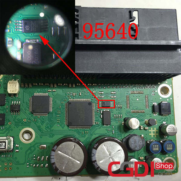
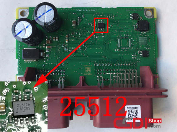
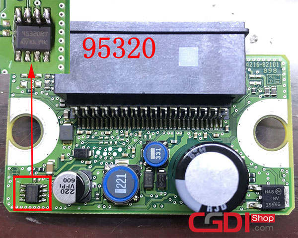
3.8-pin chip on airbag computer
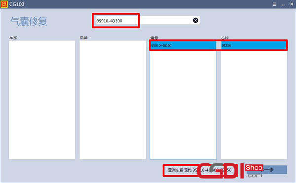
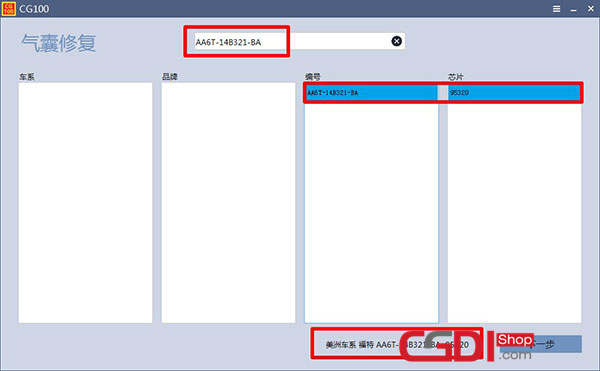
In fact, the eight-pin chip on the computer airbag is easy to find, but engraved mask and coated with a lot of waterproof glue, the most convenient way is to check the airbag number by CG100 to get the corresponding chip model, the rest of the step is to clean the chip and control the chip mask table.

That’s all! Hope it helps you!